Welcome to this in-depth tutorial on simulating an RC circuit using Xschem and Ngspice. In this guide, we’ll walk through each step necessary to create, simulate, and analyze an RC circuit, ensuring you have the skills to perform these tasks confidently.
Table of Contents
Setting Up Your Environment
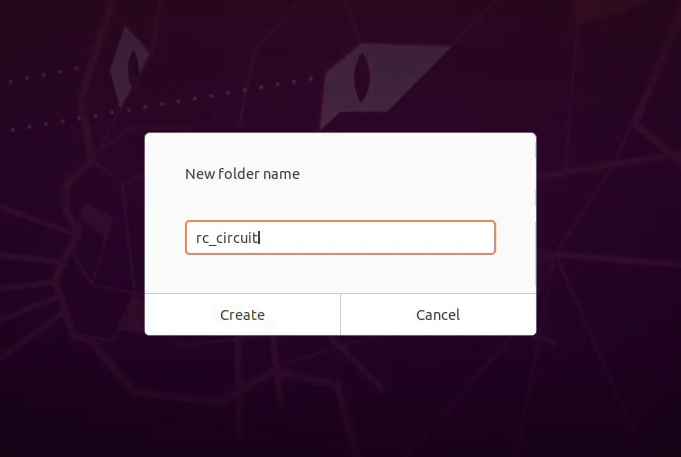
To kick things off, we need to set up our working environment. Start by creating a new directory named “rc_circuit.” This directory will house all the files related to our project.

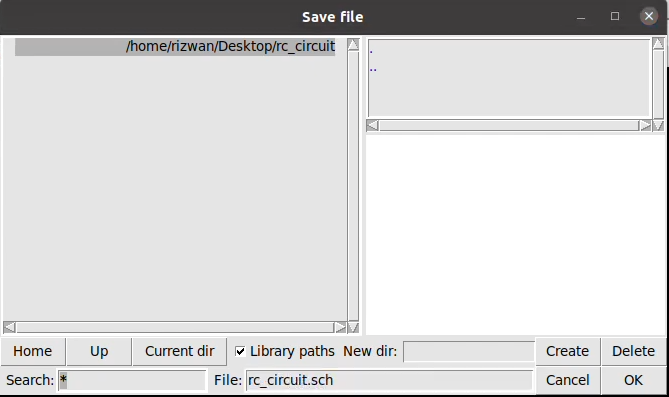
Open a terminal and navigate to your new directory. Here, you will launch Xschem. Click on the plus icon to add a new schematic workspace. When prompted to save it, name your schematic “rc_circuit.” The extension “.sch” indicates that it is a schematic file.
Inserting Components into the Schematic
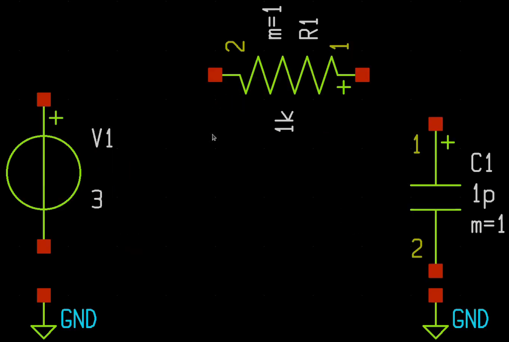
With our schematic workspace ready, we can start inserting components. Navigate to the tools menu and select “Insert Symbol” or utilize hotkeys for faster access. The “Choose Symbol” window will pop up, allowing you to select from libraries on the left side.
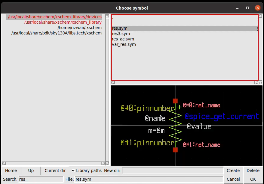
For our RC circuit, we need a resistor, capacitor, and a voltage source. Start by searching for a resistor. Type “Res” in the search bar, select the resistor symbol, and place it in your schematic. To change its orientation, use the hotkey Alt + R.
Next, repeat the process to add a capacitor. Type “Cap” in the search bar and place it in the schematic as well. For the ground symbol, use the hotkey Ctrl + I to insert a symbol, search for “ground,” and place it in the schematic. You can even copy the ground symbol by pressing C and placing it where needed.
Finally, we need to add a voltage source. Again, use Ctrl + I, search for “V Source,” and place it in the schematic. After placing all components, zoom fit your schematic by pressing F.
Connecting the Components
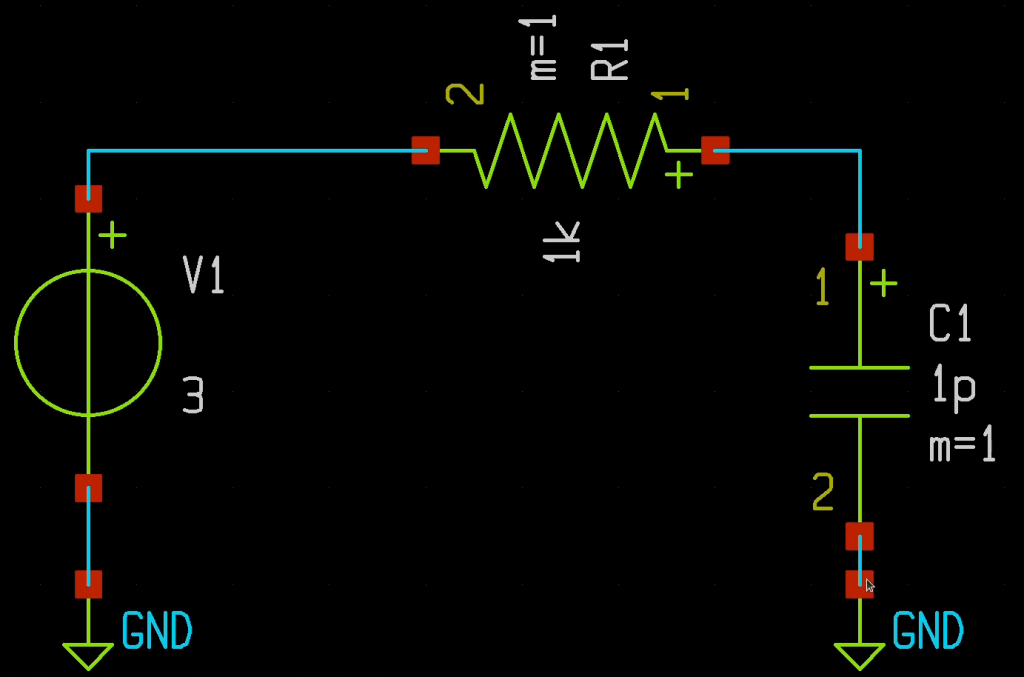
Now that we have our components, it’s time to connect them. Use the hotkey W to draw wires connecting each component. Click to start the wire and click again to stop. Make sure all components are connected correctly to form the complete circuit.
Once the circuit layout is complete, feel free to maximize the window for better visibility. You can navigate through the schematic by zooming in and out using your mouse wheel.
Defining Component Properties
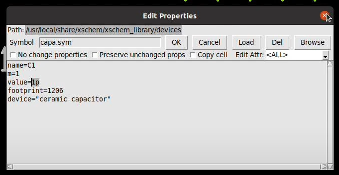
Next, we need to set the properties for each component. To edit the properties, right-click on a component and click “Edit Attributes.” Alternatively, you can use the hotkey Q. For the resistor, leave the default value of 1 Pico ohm.
Now, let’s focus on the voltage source. By default, it’s set to a DC voltage of 3 volts. We need to change it to a pulse signal. To do this, consult the Ngspice manual for the correct syntax to create a pulse. You’ll find parameters such as initial voltage, pulse voltage, delay, rise time, fall time, pulse width, and period.

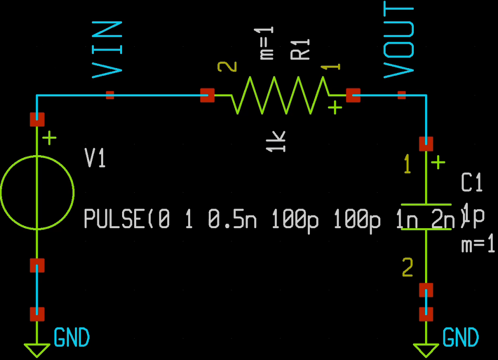
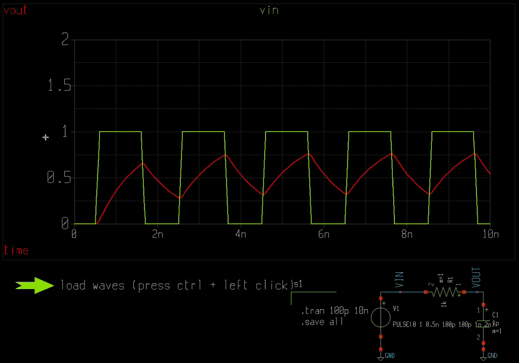
Assuming we want a pulse from 0 to 1 volt with a delay of 0.5 nanoseconds, a rise time of 100 picoseconds, a fall time of 100 picoseconds, a pulse width of 1 nanosecond, and a period of 2 nanoseconds, input these values into the voltage source’s attributes.

Labeling Wires for Clarity
For improved readability, it’s essential to label our wires. From the tools menu, select “Insert Wire Label” or use the hotkey Alt + R to add labels. Name your wires, for example, “Vin” for the input voltage and “Vout” for the output voltage. Remember, Ngspice is case-insensitive, so “Vin” and “vin” are treated the same.
Saving the Schematic
With everything in place, it’s time to save your schematic. You can do this by selecting “Save” from the menu or using the hotkey Ctrl + S.
Running the Simulation
To run the simulation, navigate to the simulation menu. By default, Ngspice is selected, so you won’t need to make any changes. First, we need to define the simulation command. Press Ctrl + I to insert a symbol and choose “Code.” This will allow you to write the simulation command.
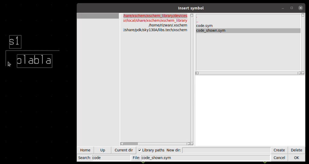
For a transient simulation, open the properties of code_shown.sym and input the command as follows:
.tran 100p 10n
.save all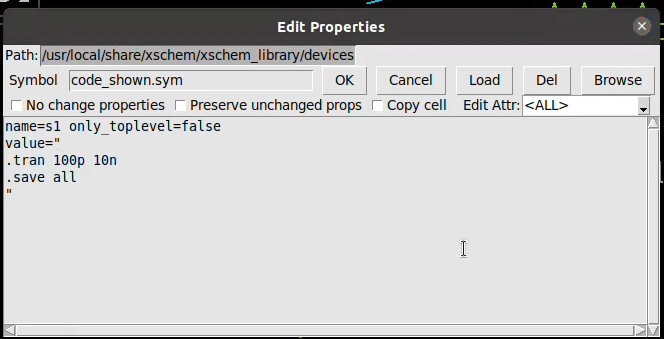
This command sets the step time to 100 picoseconds and the stop time to 10 nanoseconds. To save all waveforms, include the command to save everything as well.
Generating the Netlist and Running the Simulation
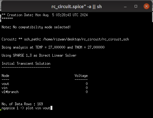
Now, click on “Netlist” to generate the netlist for your simulation. You can review it through the simulation menu by selecting “Edit Netlist,” which will display the components, simulation command, and other details.

After reviewing the netlist, click on “Simulate” to run the simulation. Once complete, use the “Plot” command to visualize the results. You can plot both the input voltage (Vin) and output voltage (Vout) waveforms.
Interpreting the Results
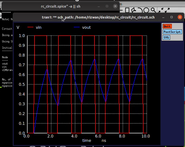
Upon plotting, you’ll observe the square wave for the input voltage and the corresponding output waveform, which should reflect the behavior of the RC circuit. The blue line typically represents the output voltage.
Enhancing Waveform Graphing Experience
The plotting interface can be a bit basic, but there’s a way to enhance your waveform graphing experience. To do this, you’ll want to write the simulation results into a raw file. This can be done by configuring Ngspice to run in batch mode.
Once you’ve set up batch mode, save your netlist and run the simulation again. This time, the output will be saved in a raw file. To view the waveforms from this file, go to the simulation menu and select “Add Waveform Graph.” Place the graph where desired.
To load the simulation data into this graph, click on the graph and follow the instructions to load the raw file. You’ll be able to visualize the waveforms and make adjustments as needed.
Final Thoughts
By following this tutorial, you’ve learned how to perform an RC circuit simulation using Xschem and Ngspice. You’ve set up your environment, created a schematic, defined component properties, ran simulations, and interpreted results.
This knowledge equips you to tackle your projects with confidence, leveraging the power of Xschem and Ngspice for effective circuit analysis and design. Whether you’re a beginner or looking to refresh your skills, this guide serves as a valuable resource for mastering circuit simulation methodologies.
Read this Article to know how to install the xschem and ngspice : Click Here
Thanks for following along, and happy simulating!