Creating a CMOS inverter is an essential skill for anyone diving into the world of electronics. In this guide, we’ll walk through the entire process of designing and simulating a CMOS inverter using Xschem with the Skywater130 Process Design Kit (PDK). Whether you’re a beginner or looking to refine your skills, this step-by-step tutorial has got you covered.
Table of Contents
Setting Up Your Environment
Before diving into the design, we need to set up our working environment. Start by opening your terminal. Right-click on your desktop and select ‘Open Terminal’. From here, you can create a dedicated directory for your inverter project.
- To create a directory, type: mkdir inverter
- Open this directory by right-clicking and selecting ‘Open in Terminal’.
Launching Xschem
Now that you have your directory, it’s time to open Xschem. If you haven’t installed Xschem or the necessary open-source tools yet, make sure to check out the installation guide. Once ready, type xschem in the terminal and hit enter.
Creating Your Schematic
Your schematic is the heart of your design. To get started, create a new tab in Xschem by clicking the + icon. If you need to close a previous tab, simply right-click on it and select ‘Close Tab’.
To save your work, either click on ‘New’ and then ‘Save’ or use the shortcut Ctrl + S. Choose your current directory and name the file inv.sch. Don’t forget, the .sch extension is necessary!
Placing Components
Next, we need to place the components for our CMOS inverter. To do this:
- Press Shift + I to open the ‘Choose Symbol’ dialog box.
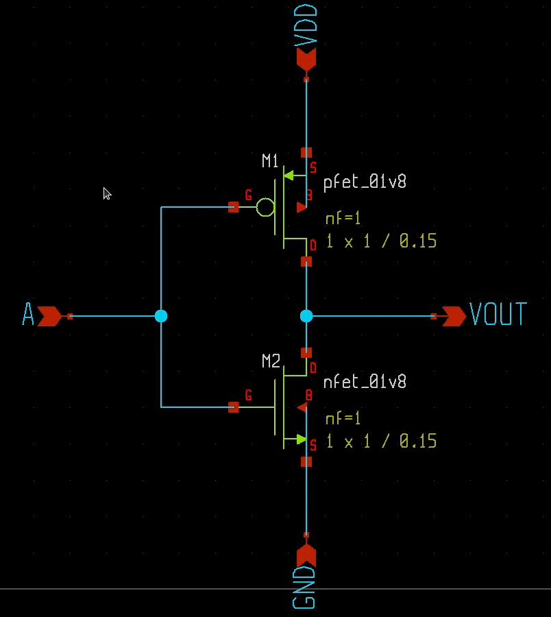
- Locate the pfet and nfet from the Skywater130 PDK. Navigate to the sky130_fd_pr directory and select the appropriate transistors.
Connecting Components
With your components placed, it’s time to connect them. To draw wires between components:
- Position your cursor where you want to connect components and press W to start drawing the wire.
- Press W again to turn the wire, and left-click to finish the drawing.
To fit your schematic view, press F to zoom out and fit everything on the screen.
Adding Terminals
Every inverter needs terminals. To add these:
- Press Shift + I again and go to the xschem_library to select ipin for the input, vdd, and ground.
- Press C to copy the symbols for vdd and gnd.
- To rotate the symbols, press Alt + R.
For the output pin, select opin from the library and follow the same steps. Rename the symbols by double-clicking on them and assigning appropriate names.
Connecting Body Terminals
It’s crucial to connect the body terminals correctly:
- For the pfet, connect the body terminal to vdd.
- For the nfet, connect the body terminal to ground.
Saving Your Schematic
Make sure to save your schematic after completing the connections. Now it’s time to convert this schematic into a symbol.
- Press A to create the symbol and click ‘OK’.
- This new symbol will be saved in the same directory as your schematic.
Creating the Testbench
With the inverter symbol ready, we can now create a testbench. Open a new tab and insert the inverter symbol:
- Press Shift + I and navigate to your current directory to select the newly created inverter symbol.
- Place the symbol on the canvas.
Adding Power Sources
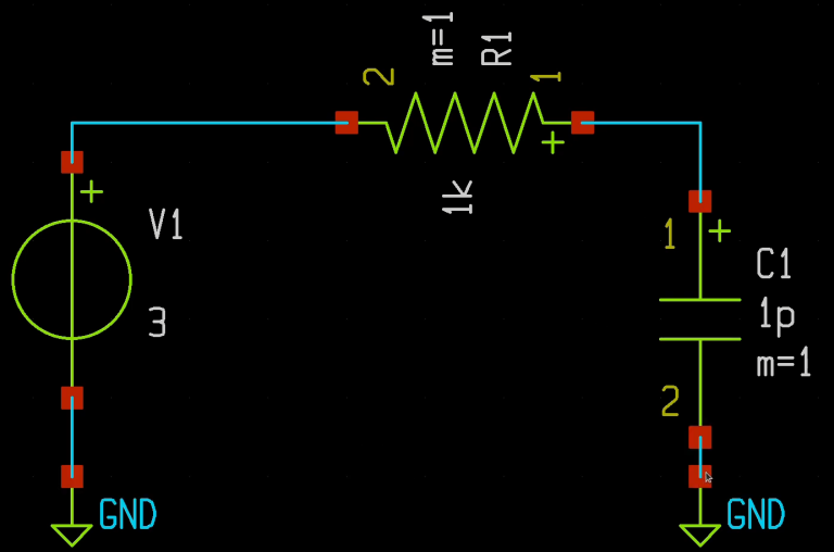
To simulate the inverter, we need power sources. Import a voltage source from the Xschem library:
- Search for vsource and place it on the canvas. You’ll need two of these, so copy the first source.
- Don’t forget to add a ground symbol and connect it to both the sources and the inverter.
To maintain a clean layout, use lab_pins for direct connections without wires. Ensure that the names of the lab pins are consistent to make the connections work.
Configuring Voltage Sources
Next, let’s assign values to our sources. Double-click on each source symbol to open its properties:
- For the inverter, use a pulse input in the ngspice format. Type: PULSE (0 1.2 0 1n 1n 1u 2u). This specifies parameters like voltage, rise time, fall time, etc.
- For the vdd source, simply set the value to 1.8.
Finalizing the Simulation Setup
Since we are using the Skywater130 PDK, we need to add a file called corner tt to help Xschem understand the symbols we’ve used. Select this file from the Sky130 PDK directory.
Specifying Simulation Type
To specify the type of simulation you want to run, select the code shown symbol from the Xschem library and place it on the canvas:
- Double-click to open its properties and specify the simulation type and duration.
Generating the Netlist
After configuring everything, save your file once more. Click on the netlist option to generate the netlist for your testbench. If no pop-up appears, your testbench is functioning correctly!
Running the Simulation
Now it’s time to run the simulation. Click on the simulate button. This will execute the simulation with the parameters you’ve set.
Plotting the Waveforms
To visualize your results, you’ll want to plot the waveforms. Type the following commands:
- plot a to see the input waveform.
- plot vout to view the output waveform.
- For both waveforms in a single window, type: plot a vout.
Conclusion
Congratulations! You’ve successfully designed and simulated a CMOS inverter using Xschem and the Skywater130 PDK. With these steps, you should now have a solid understanding of how to create and test your own circuits. Keep practicing and experimenting with different configurations to deepen your knowledge of CMOS technology.
For more tutorials and insights into the world of electronics, make sure to check out our channel and subscribe for updates!