-
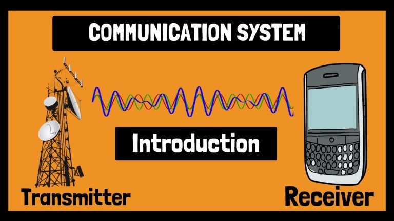
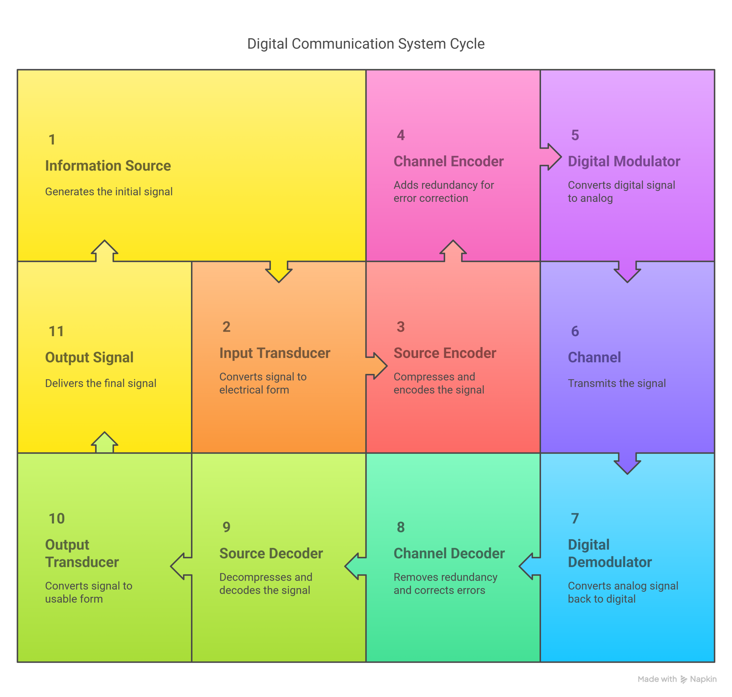
A digital communication system uses a series of blocks-from input transducer to output transducer-to reliably transmit information across noisy channels.
-
Key stages include source and channel encoding, modulation, and decoding, each playing a unique role in data compression, error correction, and signal transformation.
-
Understanding the block diagram helps diagnose, optimize, and innovate in fields like telecommunications, broadcasting, and data networking.
For a clear visual walkthrough, check out this video:
Why Block Diagrams Matter in Digital Communication
When I first started learning about digital communication, the block diagram was my roadmap. It breaks down the entire process-from capturing information to delivering it at the other end-into manageable, logical steps. Each block has a specific function, and together, they ensure that your message, whether it’s a text, a song, or a video, gets from point A to point B with minimal error.
The Big Picture: Block Diagram Overview
Let’s walk through a typical digital communication system, block by block. Here’s a simplified view:
| Transmitter Side | Channel | Receiver Side |
|---|---|---|
| Information Source | Physical Medium | Digital Demodulator |
| Input Transducer/Formatter | Channel Decoder | |
| Source Encoder | Source Decoder | |
| Channel Encoder | Output Transducer/Deformatter | |
| Digital Modulator/Baseband Proc | Output Signal |
Step-by-Step Breakdown
1. Information Source and Input Transducer
Everything starts with an information source. This could be a person speaking, a computer file, a camera, or any device that generates data. If the information isn’t already in electrical form, an input transducer-like a microphone for audio or a camera sensor for video-converts it into an electrical signal.
If the source is already digital, like a computer file, you might skip this step or use a formatter to prepare the data for transmission.
2. Source Encoder
The source encoder’s job is to compress data, removing unnecessary or redundant bits. Think of it as zipping a file before emailing it. This step is crucial for efficient bandwidth usage. Common techniques include Huffman coding for digital data and adaptive delta modulation for analog signals.
-
Goal: Reduce data size without losing essential information.
-
Output: Compressed digital data, called the source code.
3. Channel Encoder
Now, the compressed data needs protection from errors. The channel encoder adds redundancy-extra bits that help detect and correct errors introduced during transmission. Techniques like block coding and convolutional coding are widely used.
-
Goal: Make the data robust against noise and interference.
-
Output: Channel code-the original data plus error-correcting bits.
4. Baseband Processor and Digital Modulator
Before data can travel over a physical medium, it often needs to be converted into a form suitable for transmission. The baseband processor handles tasks like pulse shaping and line coding for low-speed or short-distance links.
For longer distances or high-speed links, a digital modulator steps in. It takes the digital signal and modulates it onto a high-frequency carrier wave using methods like Amplitude Shift Keying (ASK) or Frequency Shift Keying (FSK).
-
Goal: Prepare the signal for efficient, reliable transmission over the channel.
-
Output: Modulated electromagnetic wave.
5. Channel (Physical Medium)
The channel is the path the signal travels-air, cable, fiber optics, or even space. This is where most noise and distortion creep in. The channel’s properties greatly affect the quality and reliability of communication.
-
Common channel issues: Noise, interference, fading, and attenuation.
6. Receiver Side: Demodulation and Decoding
At the receiver, the process reverses:
a. Digital Demodulator
The receiver’s first job is to recover the digital signal from the modulated carrier. The digital demodulator strips away the carrier, leaving the baseband digital signal.
b. Channel Decoder
Next, the channel decoder uses the redundancy added earlier to detect and correct errors. This is where the system recovers from any noise-induced mistakes.
c. Source Decoder
The source decoder decompresses the data, restoring it to its original form. It undoes whatever compression or formatting the source encoder performed.
d. Output Transducer/Deformatter
Finally, the output transducer converts the electrical signal back into a human-usable form-like a speaker producing sound, a screen displaying video, or a printer creating a document.
Block Diagram in Action: Visual Summary
Here’s a simplified block diagram for quick reference:
Key Functions of Each Block
| Block | Main Function | Example Techniques |
|---|---|---|
| Input Transducer | Converts physical data to electrical signal | Microphone, camera sensor |
| Source Encoder | Compresses data, removes redundancy | Huffman coding, delta modulation |
| Channel Encoder | Adds error correction bits | Block code, convolutional code |
| Digital Modulator | Converts digital data to modulated carrier | ASK, FSK, PSK |
| Channel | Transmits signal, adds noise | Air, cable, fiber |
| Digital Demodulator | Recovers baseband digital signal | Demodulation circuits |
| Channel Decoder | Corrects transmission errors | Viterbi decoder, parity checks |
| Source Decoder | Decompresses data | Inverse Huffman, delta decoding |
| Output Transducer | Converts electrical signal to original form | Speaker, display, printer |
Why This Matters: Real-World Applications
Digital communication systems are everywhere:
-
Telecommunications: Cell phones, internet, satellite links
-
Broadcasting: Digital TV, radio
-
Data Networking: Wi-Fi, Ethernet, Bluetooth
-
Remote Sensing: Weather satellites, GPS
Understanding the block diagram helps troubleshoot issues, optimize performance, and design new systems. For example, if there’s too much noise, you might improve the channel encoder or use a better modulation scheme.
Common Questions
Why add redundancy if we just removed it?
Source encoding removes unnecessary redundancy to save bandwidth, while channel encoding adds useful redundancy for error correction. Both are essential but serve different goals.
What’s the difference between analog and digital communication block diagrams?
Analog systems skip some blocks, like source/channel encoding, and use analog modulators/demodulators. Digital systems add more processing for reliability and efficiency.
Can you skip blocks in some cases?
Yes. For example, if the channel is very clean, you might not need heavy error correction. If the source is already digital, you might not need a formatter.
Key Takeaways
-
Every block in the digital communication system has a unique role, from compressing data to correcting errors and converting signals for transmission.
-
The block diagram provides a clear blueprint for understanding, troubleshooting, and optimizing digital communication systems.
-
Mastering this diagram is foundational for anyone working in telecom, networking, or any field that relies on reliable digital information transfer.
A strong grasp of this block structure is the first step to becoming fluent in the language of digital communication, whether you’re designing new systems or just trying to understand how your favorite tech works behind the scenes.